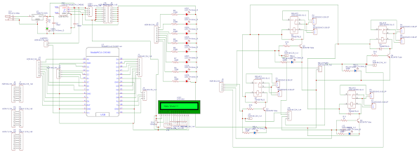
In an age where technology has taken center stage in our
daily lives, why not bring that innovation into the heart of your home? Home
automation has revolutionized the way we interact with our living spaces,
making them smarter, more efficient, and even eco-friendly. In this
comprehensive guide, we'll explore the world of home automation using NodeMCU
ESP32 Wroom, coupled with a 16x2 LCD display, a 4-channel relay module, sensor
interfaces, and 8 LEDs for binary checks.
NodeMCU ESP32 Wroom: Learn about this versatile
microcontroller and why it's the perfect choice for home automation projects.
Required Components: We'll list all the materials and
components you'll need for this project.
Connecting the 16x2 LCD Display: Step-by-step instructions
on wiring and configuring the LCD display for your NodeMCU ESP32.
Integrating the 4-Channel Relay: Understand how to control
electrical appliances using relays and connect them to your NodeMCU.
Temperature and Humidity Sensors: Discover how to interface
these sensors to create a comfortable living environment.
Motion Sensors: Learn how to add security and energy-saving
features to your smart home.
Binary LED Indicators: Implement an 8-LED array for binary
checks and notifications, adding a visual dimension to your home automation
system.
Arduino IDE Setup: Configure your Arduino IDE for NodeMCU
ESP32 programming.
Writing the Code: We'll provide code snippets and explain
the logic behind programming your home automation system.
*/
#include <Arduino.h>
// There are two ways to make this sketch work:
// By physically connecting the pins 4 and 5 and then create a physical UART loopback,
// Or by using the internal IO_MUX to connect the TX signal to the RX pin, creating the
// same loopback internally.
#define USE_INTERNAL_PIN_LOOPBACK 1 // 1 uses the internal loopback, 0 for wiring pins 4 and 5 externally
#define DATA_SIZE 26 // 26 bytes is a lower than RX FIFO size (127 bytes)
#define BAUD 9600 // Any baudrate from 300 to 115200
#define TEST_UART 1 // Serial1 will be used for the loopback testing with different RX FIFO FULL values
#define RXPIN 4 // GPIO 4 => RX for Serial1
#define TXPIN 5 // GPIO 5 => TX for Serial1
uint8_t fifoFullTestCases[] = {120, 20, 5, 1};
// volatile declaration will avoid any compiler optimization when reading variable values
volatile size_t sent_bytes = 0, received_bytes = 0;
void onReceiveFunction(void) {
// This is a callback function that will be activated on UART RX events
size_t available = Serial1.available();
received_bytes += available;
Serial.printf("onReceive Callback:: There are %d bytes available: ", available);
while (available --) {
Serial.print((char)Serial1.read());
}
Serial.println();
}
void setup() {
// UART0 will be used to log information into Serial Monitor
Serial.begin(115200);
// UART1 will have its RX<->TX cross connected
// GPIO4 <--> GPIO5 using external wire
Serial1.begin(BAUD, SERIAL_8N1, RXPIN, TXPIN); // Rx = 4, Tx = 5 will work for ESP32, S2, S3 and C3
#if USE_INTERNAL_PIN_LOOPBACK
uart_internal_loopback(TEST_UART, RXPIN);
#endif
for (uint8_t i = 0; i < sizeof(fifoFullTestCases); i++) {
Serial.printf("\n\n================================\nTest Case #%d\n================================\n", i + 1);
// onReceive callback will be called on FIFO Full and RX timeout - default behaviour
testAndReport(fifoFullTestCases[i], false);
}
Serial.printf("\n\n================================\nTest Case #6\n================================\n");
// onReceive callback will be called just on RX timeout - using onlyOnTimeout = true
// FIFO Full parameter (5 bytes) won't matter for the execution of this test case
// because onReceive() uses only RX Timeout to be activated
testAndReport(5, true);
}
void loop() {
}
void testAndReport(uint8_t fifoFull, bool onlyOnTimeOut) {
// Let's send 125 bytes from Serial1 rx<->tx and mesaure time using diferent FIFO Full configurations
received_bytes = 0;
sent_bytes = DATA_SIZE; // 26 characters
uint8_t dataSent[DATA_SIZE + 1];
dataSent[DATA_SIZE] = '\0'; // string null terminator, for easy printing.
// initialize all data
for (uint8_t i = 0; i < DATA_SIZE; i++) {
dataSent[i] = 'A' + i; // fill it with characters A..Z
}
Serial.printf("\nTesting onReceive for receiving %d bytes at %d baud, using RX FIFO Full = %d.\n", sent_bytes, BAUD, fifoFull);
if (onlyOnTimeOut) {
Serial.println("onReceive is called just on RX Timeout!");
} else {
Serial.println("onReceive is called on both FIFO Full and RX Timeout events.");
}
Serial.flush(); // wait Serial FIFO to be empty and then spend almost no time processing it
Serial1.setRxFIFOFull(fifoFull); // testing diferent result based on FIFO Full setup
Serial1.onReceive(onReceiveFunction, onlyOnTimeOut); // sets a RX callback function for Serial 1
sent_bytes = Serial1.write(dataSent, DATA_SIZE); // ESP32 TX FIFO is about 128 bytes, 125 bytes will fit fine
Serial.printf("\nSent String: %s\n", dataSent);
while (received_bytes < sent_bytes) {
// just wait for receiving all byte in the callback...
}
Serial.printf("\nIt has sent %d bytes from Serial1 TX to Serial1 RX\n", sent_bytes);
Serial.printf("onReceive() has read a total of %d bytes\n", received_bytes);
Serial.println("========================\nFinished!");
Serial1.onReceive(NULL); // resets/disables the RX callback function for Serial 1
}
Testing Your System: Learn how to test each component to
ensure it's working as expected.
Troubleshooting Tips: Discover common issues and how to
troubleshoot them effectively.
Creating Your Smart Home: Reflect on the transformation your
home has undergone through automation.
In this ultimate home automation guide, we've unlocked the
potential of NodeMCU ESP32 Wroom and several key components to create a smart
and efficient living space. Whether you're a beginner or an IoT enthusiast,
this project will not only upgrade your home but also enhance your technical
skills.
Stay tuned for regular updates, tips, and tricks in the
world of IoT and home automation. Your journey towards a smarter home starts
here.


No comments