

🔋 DIY Solar-Based Mini IPS at Home | Auto Load Changeover Circuit for 12V DC Fan/Light
🔋 DIY Solar-Based Mini IPS at Home | Auto Load Changeover Circuit for 12V DC Fan/Light

$5 10pcs 1-2 layer PCB Order from PCBWay: https://www.pcbway.com/?from=technology4power
If you're looking for an easy and affordable solution to keep your 12V DC fan or light running even when solar power is unavailable, this project is perfect for you! In this guide, you'll learn how to build a DIY Solar Mini IPS (Instant Power Supply) with auto load changeover. It uses solar energy as the primary source and automatically switches to battery backup when solar is off.
🧰 Components Required
12V Solar Panel (20W to 40W)
12V Charge Controller (PWM or MPPT)
12V 7Ah or 12Ah Lead Acid Battery
Relay Module (SRD-05VDC-SL-C)
1 Diode 6A10
1 Diode 1N4007
2 Resistors (1K ohm)
3 Red LEDs (5mm)
DC Power Socket
Jumper Wires
2-pin Screw Connectors
Plastic Enclosure (for safety)
🔌 Circuit Purpose
The provided changeover circuit detects when solar power is available. If yes, it powers the load (fan/light) using solar. If not, it automatically switches the load to battery power. This happens using a relay that intelligently changes the connection without any manual action.
📷 Circuit Diagram
$5 10pcs 1-2 layer PCB Order from PCBWay: https://www.pcbway.com/?from=technology4power
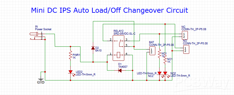
You can refer to the circuit you provided in the image titled:
"Mini DC IPS Auto Load/Off Changeover Circuit"
This schematic includes:
Relay module
Diodes (6A10 and 1N4007)
LEDs for status indication
Power and battery connectors
🔧 How the Changeover Circuit Works
- The "IN" connector receives 12V DC from the solar charge controller (which gets power from the solar panel).
- The relay is powered using this solar voltage. When 12V is present, the relay activates.
- When the relay is activated, it connects the load to the solar power.
- When solar power is unavailable (cloudy or nighttime), the relay deactivates.
- In this case, the load automatically switches to battery power via the relay's NC (Normally Closed) terminal.
- D2 (6A10 diode) prevents current backflow from the battery to the solar side.
- D1 (1N4007) acts as a flyback diode to protect the relay coil.
- LEDs indicate power status:
- LED1 shows solar is supplying the load.
- LED2 shows battery is supplying the load.
- LED3 shows power from solar input.
🛠️ How to Build the Circuit
- Start by placing the relay on a breadboard or solderable PCB.
- Connect the IN terminal to the 12V solar output from the charge controller.
- Connect the BAT terminal to the 12V battery output.
- Connect the relay as follows:
- COM (common) to the load positive terminal.
- NO (Normally Open) to the IN (solar side).
- NC (Normally Closed) to the BAT (battery side).
- Connect D2 (6A10) in series with the IN terminal to protect from reverse current.
- Place D1 (1N4007) across the relay coil (pin 1 and 2).
- Add LED1 and LED2 with 1K resistors to show active source (solar or battery).
- Add LED3 directly across IN terminal and GND with a 1K resistor.
- Connect your 12V fan or light to the LOAD terminal.
- Place everything inside a plastic enclosure and label the terminals.
🔄 Load Behavior (Auto Switching)
- When solar power is ON (daytime), relay stays energized, load runs from solar.
- When solar power is OFF (night), relay de-energizes, load automatically switches to battery.
- No manual switching is needed—everything happens automatically.
⚡ Suitable Loads
12V DC table fan (up to 15W)
12V DC LED light (5W to 10W)
Mini USB Air Cooler (with buck converter to 5V)
⚠️ Do not connect high power AC appliances or large inverters to this system.
🏠 Ideal Usage
Homes in rural areas without grid power
Emergency backup light system
Nighttime cooling with small DC fans
Solar educational projects for students
📦 Setup Tips
Use strong wires and proper connectors for safety.
Ensure battery and circuit are enclosed in a well-ventilated box.
Always test with a multimeter before connecting final loads.
Label all inputs and outputs clearly for easy identification.
🎥 Video Tutorial
$5 10pcs 1-2 layer PCB Order from PCBWay: https://www.pcbway.com/?from=technology4power
📘 Conclusion
With this DIY Solar IPS project, you can build a smart auto-switching power backup system that runs 12V DC loads like fans and lights—perfect for off-grid living or tackling load shedding. This circuit is cheap, compact, and efficient. Try building it at home today!


No comments