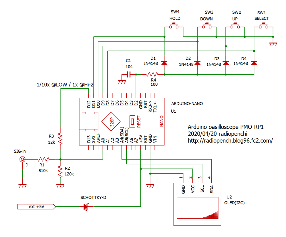
Design the PCB to make the connections tidy and compact. You can order a custom PCB from PCBway. It will include the necessary connections for the Arduino Nano, resistors, buttons, and power supply.
Once the PCB arrives, the components will be soldered as per the design.
Now, it’s time to bring the oscilloscope to life! Here’s a snippet of the button handling code for signal navigation:
#include <Wire.h>
#include <Adafruit_GFX.h>
//#include <Adafruit_SSD1306.h>
#include <Adafruit_SH1106.h> // https://github.com/wonho-maker/Adafruit_SH1106
#include <EEPROM.h>
#define SCREEN_WIDTH 128 // OLED display width
#define SCREEN_HEIGHT 64 // OLED display height
#define REC_LENG 200 // size of wave data buffer
#define MIN_TRIG_SWING 5 // minimum trigger swing.(Display "Unsync" if swing smaller than this value
// Declaration for an SSD1306 display connected to I2C (SDA, SCL pins)
#define OLED_RESET -1 // Reset pin # (or -1 if sharing Arduino reset pin)
//Adafruit_SSD1306 oled(SCREEN_WIDTH, SCREEN_HEIGHT, &Wire, OLED_RESET); // device name is oled
Adafruit_SH1106 oled(OLED_RESET); // use this when SH1106
// Range name table (those are stored in flash memory)
const char vRangeName[10][5] PROGMEM = {"A50V", "A 5V", " 50V", " 20V", " 10V", " 5V", " 2V", " 1V", "0.5V", "0.2V"}; // Vertical display character (number of characters including \ 0 is required)
const char * const vstring_table[] PROGMEM = {vRangeName[0], vRangeName[1], vRangeName[2], vRangeName[3], vRangeName[4], vRangeName[5], vRangeName[6], vRangeName[7], vRangeName[8], vRangeName[9]};
const char hRangeName[10][6] PROGMEM = {"200ms", "100ms", " 50ms", " 20ms", " 10ms", " 5ms", " 2ms", " 1ms", "500us", "200us"}; // Hrizontal display characters
const char * const hstring_table[] PROGMEM = {hRangeName[0], hRangeName[1], hRangeName[2], hRangeName[3], hRangeName[4], hRangeName[5], hRangeName[6], hRangeName[7], hRangeName[8], hRangeName[9]};
const PROGMEM float hRangeValue[] = { 0.2, 0.1, 0.05, 0.02, 0.01, 0.005, 0.002, 0.001, 0.5e-3, 0.2e-3}; // horizontal range value in second. ( = 25pix on screen)
int waveBuff[REC_LENG]; // wave form buffer (RAM remaining capacity is barely)
char chrBuff[8]; // display string buffer
char hScale[] = "xxxAs"; // horizontal scale character
char vScale[] = "xxxx"; // vartical scale
float lsb5V = 0.00566826; // sensivity coefficient of 5V range. std=0.00563965 1.1*630/(1024*120)
float lsb50V = 0.05243212; // sensivity coefficient of 50V range. std=0.0512898 1.1*520.91/(1024*10.91)
volatile int vRange; // V-range number 0:A50V, 1:A 5V, 2:50V, 3:20V, 4:10V, 5:5V, 6:2V, 7:1V, 8:0.5V, 9:0.2V
volatile int hRange; // H-range nubmer 0:200ms, 1:100ms, 2:50ms, 3:20ms, 4:10ms, 5:5ms, 6;2ms, 7:1ms, 8:500us, 9;200us
volatile int trigD; // trigger slope flag, 0:positive 1:negative
volatile int scopeP; // operation scope position number. 0:Veratical, 1:Hrizontal, 2:Trigger slope
volatile boolean hold = false; // hold flag
volatile boolean switchPushed = false; // flag of switch pusshed !
volatile int saveTimer; // remaining time for saving EEPROM
int timeExec; // approx. execution time of current range setting (ms)
int dataMin; // buffer minimum value (smallest=0)
int dataMax; // maximum value (largest=1023)
int dataAve; // 10 x average value (use 10x value to keep accuracy. so, max=10230)
int rangeMax; // buffer value to graph full swing
int rangeMin; // buffer value of graph botto
int rangeMaxDisp; // display value of max. (100x value)
int rangeMinDisp; // display value if min.
int trigP; // trigger position pointer on data buffer
boolean trigSync; // flag of trigger detected
int att10x; // 10x attenetor ON (effective when 1)
float waveFreq; // frequency (Hz)
float waveDuty; // duty ratio (%)
void setup() {
pinMode(2, INPUT_PULLUP); // button pussed interrupt (int.0 IRQ)
pinMode(8, INPUT_PULLUP); // Select button
pinMode(9, INPUT_PULLUP); // Up
pinMode(10, INPUT_PULLUP); // Down
pinMode(11, INPUT_PULLUP); // Hold
pinMode(12, INPUT); // 1/10 attenuator(Off=High-Z, Enable=Output Low)
pinMode(13, OUTPUT); // LED
// oled.begin(SSD1306_SWITCHCAPVCC, 0x3C) { // select 3C or 3D (set your OLED I2C address)
oled.begin(SH1106_SWITCHCAPVCC, 0x3C); // use this when SH1106
auxFunctions(); // Voltage measure (never return)
loadEEPROM(); // read last settings from EEPROM
analogReference(INTERNAL); // ADC full scale = 1.1V
attachInterrupt(0, pin2IRQ, FALLING); // activate IRQ at falling edge mode
startScreen(); // display start message
}
void loop() {
setConditions(); // set measurment conditions
digitalWrite(13, HIGH); // flash LED
readWave(); // read wave form and store into buffer memory
digitalWrite(13, LOW); // stop LED
setConditions(); // set measurment conditions again (reflect change during measure)
dataAnalize(); // analize data
writeCommonImage(); // write fixed screen image (2.6ms)
plotData(); // plot waveform (10-18ms)
dispInf(); // display information (6.5-8.5ms)
oled.display(); // send screen buffer to OLED (37ms)
saveEEPROM(); // save settings to EEPROM if necessary
while (hold == true) { // wait if Hold flag ON
dispHold();
delay(10);
} // loop cycle speed = 60-470ms (buffer size = 200)
}
void setConditions() { // measuring condition setting
// get range name from PROGMEM
strcpy_P(hScale, (char*)pgm_read_word(&(hstring_table[hRange]))); // H range name
strcpy_P(vScale, (char*)pgm_read_word(&(vstring_table[vRange]))); // V range name
switch (vRange) { // setting of Vrange
case 0: { // Auto50V range
att10x = 1; // use input attenuator
break;
}
case 1: { // Auto 5V range
att10x = 0; // no attenuator
break;
}
case 2: { // 50V range
rangeMax = 50 / lsb50V; // set full scale pixcel count number
rangeMaxDisp = 5000; // vartical scale (set100x value)
rangeMin = 0;
rangeMinDisp = 0;
att10x = 1; // use input attenuator
break;
}
case 3: { // 20V range
rangeMax = 20 / lsb50V; // set full scale pixcel count number
rangeMaxDisp = 2000;
rangeMin = 0;
rangeMinDisp = 0;
att10x = 1; // use input attenuator
break;
}
case 4: { // 10V range
rangeMax = 10 / lsb50V; // set full scale pixcel count number
rangeMaxDisp = 1000;
rangeMin = 0;
rangeMinDisp = 0;
att10x = 1; // use input attenuator
break;
}
case 5: { // 5V range
rangeMax = 5 / lsb5V; // set full scale pixcel count number
rangeMaxDisp = 500;
rangeMin = 0;
rangeMinDisp = 0;
att10x = 0; // no input attenuator
break;
}
case 6: { // 2V range
rangeMax = 2 / lsb5V; // set full scale pixcel count number
rangeMaxDisp = 200;
rangeMin = 0;
rangeMinDisp = 0;
att10x = 0; // no input attenuator
break;
}
case 7: { // 1V range
rangeMax = 1 / lsb5V; // set full scale pixcel count number
rangeMaxDisp = 100;
rangeMin = 0;
rangeMinDisp = 0;
att10x = 0; // no input attenuator
break;
}
case 8: { // 0.5V range
rangeMax = 0.5 / lsb5V; // set full scale pixcel count number
rangeMaxDisp = 50;
rangeMin = 0;
rangeMinDisp = 0;
att10x = 0; // no input attenuator
break;
}
case 9: { // 0.5V range
rangeMax = 0.2 / lsb5V; // set full scale pixcel count number
rangeMaxDisp = 20;
rangeMin = 0;
rangeMinDisp = 0;
att10x = 0; // no input attenuator
break;
}
}
}
void writeCommonImage() { // Common screen image drawing
oled.clearDisplay(); // erase all(0.4ms)
oled.setTextColor(WHITE); // write in white character
oled.setCursor(85, 0); // Start at top-left corner
oled.println(F("av v")); // 1-st line fixed characters
oled.drawFastVLine(26, 9, 55, WHITE); // left vartical line
oled.drawFastVLine(127, 9, 3, WHITE); // right vrtical line up
oled.drawFastVLine(127, 61, 3, WHITE); // right vrtical line bottom
oled.drawFastHLine(24, 9, 7, WHITE); // Max value auxiliary mark
oled.drawFastHLine(24, 36, 2, WHITE);
oled.drawFastHLine(24, 63, 7, WHITE);
oled.drawFastHLine(51, 9, 3, WHITE); // Max value auxiliary mark
oled.drawFastHLine(51, 63, 3, WHITE);
oled.drawFastHLine(76, 9, 3, WHITE); // Max value auxiliary mark
oled.drawFastHLine(76, 63, 3, WHITE);
oled.drawFastHLine(101, 9, 3, WHITE); // Max value auxiliary mark
oled.drawFastHLine(101, 63, 3, WHITE);
oled.drawFastHLine(123, 9, 5, WHITE); // right side Max value auxiliary mark
oled.drawFastHLine(123, 63, 5, WHITE);
for (int x = 26; x <= 128; x += 5) {
oled.drawFastHLine(x, 36, 2, WHITE); // Draw the center line (horizontal line) with a dotted line
}
for (int x = (127 - 25); x > 30; x -= 25) {
for (int y = 10; y < 63; y += 5) {
oled.drawFastVLine(x, y, 2, WHITE); // Draw 3 vertical lines with dotted lines
}
}
}
void readWave() { // Record waveform to memory array
if (att10x == 1) { // if 1/10 attenuator required
pinMode(12, OUTPUT); // assign attenuator controle pin to OUTPUT,
digitalWrite(12, LOW); // and output LOW (output 0V)
} else { // if not required
pinMode(12, INPUT); // assign the pin input (Hi-z)
}
switchPushed = false; // Clear switch operation flag
switch (hRange) { // set recording conditions in accordance with the range number
case 0: { // 200ms range
timeExec = 1600 + 60; // Approximate execution time(ms) Used for countdown until saving to EEPROM
ADCSRA = ADCSRA & 0xf8; // clear bottom 3bit
ADCSRA = ADCSRA | 0x07; // dividing ratio = 128 (default of Arduino)
for (int i = 0; i < REC_LENG; i++) { // up to rec buffer size
waveBuff[i] = analogRead(0); // read and save approx 112us
delayMicroseconds(7888); // timing adjustment
if (switchPushed == true) { // if any switch touched
switchPushed = false;
break; // abandon record(this improve response)
}
}
break;
}
case 1: { // 100ms range
timeExec = 800 + 60; // Approximate execution time(ms) Used for countdown until saving to EEPROM
ADCSRA = ADCSRA & 0xf8; // clear bottom 3bit
ADCSRA = ADCSRA | 0x07; // dividing ratio = 128 (default of Arduino)
for (int i = 0; i < REC_LENG; i++) { // up to rec buffer size
waveBuff[i] = analogRead(0); // read and save approx 112us
// delayMicroseconds(3888); // timing adjustmet
delayMicroseconds(3860); // timing adjustmet tuned
if (switchPushed == true) { // if any switch touched
switchPushed = false;
break; // abandon record(this improve response)
}
}
break;
}
case 2: { // 50ms range
timeExec = 400 + 60; // Approximate execution time(ms)
ADCSRA = ADCSRA & 0xf8; // clear bottom 3bit
ADCSRA = ADCSRA | 0x07; // dividing ratio = 128 (default of Arduino)
for (int i = 0; i < REC_LENG; i++) { // up to rec buffer size
waveBuff[i] = analogRead(0); // read and save approx 112us
// delayMicroseconds(1888); // timing adjustmet
delayMicroseconds(1880); // timing adjustmet tuned
if (switchPushed == true) { // if any switch touched
break; // abandon record(this improve response)
}
}
break;
}
case 3: { // 20ms range
timeExec = 160 + 60; // Approximate execution time(ms)
ADCSRA = ADCSRA & 0xf8; // clear bottom 3bit
ADCSRA = ADCSRA | 0x07; // dividing ratio = 128 (default of Arduino)
for (int i = 0; i < REC_LENG; i++) { // up to rec buffer size
waveBuff[i] = analogRead(0); // read and save approx 112us
// delayMicroseconds(688); // timing adjustmet
delayMicroseconds(686); // timing adjustmet tuned
if (switchPushed == true) { // if any switch touched
break; // abandon record(this improve response)
}
}
break;
}
case 4: { // 10ms range
timeExec = 80 + 60; // Approximate execution time(ms)
ADCSRA = ADCSRA & 0xf8; // clear bottom 3bit
ADCSRA = ADCSRA | 0x07; // dividing ratio = 128 (default of Arduino)
for (int i = 0; i < REC_LENG; i++) { // up to rec buffer size
waveBuff[i] = analogRead(0); // read and save approx 112us
// delayMicroseconds(288); // timing adjustmet
delayMicroseconds(287); // timing adjustmet tuned
if (switchPushed == true) { // if any switch touched
break; // abandon record(this improve response)
}
}
break;
}
case 5: { // 5ms range
timeExec = 40 + 60; // Approximate execution time(ms)
ADCSRA = ADCSRA & 0xf8; // clear bottom 3bit
ADCSRA = ADCSRA | 0x07; // dividing ratio = 128 (default of Arduino)
for (int i = 0; i < REC_LENG; i++) { // up to rec buffer size
waveBuff[i] = analogRead(0); // read and save approx 112μs
// delayMicroseconds(88); // timing adjustmet
delayMicroseconds(87); // timing adjustmet tuned
if (switchPushed == true) { // if any switch touched
break; // abandon record(this improve response)
}
}
break;
}
case 6: { // 2ms range
timeExec = 16 + 60; // Approximate execution time(ms)
ADCSRA = ADCSRA & 0xf8; // clear bottom 3bit
ADCSRA = ADCSRA | 0x06; // dividing ratio = 64 (0x1=2, 0x2=4, 0x3=8, 0x4=16, 0x5=32, 0x6=64, 0x7=128)
for (int i = 0; i < REC_LENG; i++) { // up to rec buffer size
waveBuff[i] = analogRead(0); // read and save approx 56us
// delayMicroseconds(24); // timing adjustmet
delayMicroseconds(23); // timing adjustmet tuned
}
break;
}
case 7: { // 1ms range
timeExec = 8 + 60; // Approximate execution time(ms)
ADCSRA = ADCSRA & 0xf8; // clear bottom 3bit
ADCSRA = ADCSRA | 0x05; // dividing ratio = 16 (0x1=2, 0x2=4, 0x3=8, 0x4=16, 0x5=32, 0x6=64, 0x7=128)
for (int i = 0; i < REC_LENG; i++) { // up to rec buffer size
waveBuff[i] = analogRead(0); // read and save approx 28us
// delayMicroseconds(12); // timing adjustmet
delayMicroseconds(10); // timing adjustmet tuned
}
break;
}
case 8: { // 500us range
timeExec = 4 + 60; // Approximate execution time(ms)
ADCSRA = ADCSRA & 0xf8; // clear bottom 3bit
ADCSRA = ADCSRA | 0x04; // dividing ratio = 16(0x1=2, 0x2=4, 0x3=8, 0x4=16, 0x5=32, 0x6=64, 0x7=128)
for (int i = 0; i < REC_LENG; i++) { // up to rec buffer size
waveBuff[i] = analogRead(0); // read and save approx 16us
delayMicroseconds(4); // timing adjustmet
// time fine adjustment 0.0625 x 8 = 0.5us(nop=0.0625us @16MHz)
asm("nop"); asm("nop"); asm("nop"); asm("nop"); asm("nop"); asm("nop"); asm("nop"); asm("nop");
}
break;
}
case 9: { // 200us range
timeExec = 2 + 60; // Approximate execution time(ms)
ADCSRA = ADCSRA & 0xf8; // clear bottom 3bit
ADCSRA = ADCSRA | 0x02; // dividing ratio = 4(0x1=2, 0x2=4, 0x3=8, 0x4=16, 0x5=32, 0x6=64, 0x7=128)
for (int i = 0; i < REC_LENG; i++) { // up to rec buffer size
waveBuff[i] = analogRead(0); // read and save approx 6us
// time fine adjustment 0.0625 * 20 = 1.25us (nop=0.0625us @16MHz)
asm("nop"); asm("nop"); asm("nop"); asm("nop"); asm("nop"); asm("nop"); asm("nop"); asm("nop"); asm("nop"); asm("nop");
asm("nop"); asm("nop"); asm("nop"); asm("nop"); asm("nop"); asm("nop"); asm("nop"); asm("nop"); asm("nop"); asm("nop");
}
break;
}
}
}
void dataAnalize() { // get various information from wave form
int d;
long sum = 0;
// search max and min value
dataMin = 1023; // min value initialize to big number
dataMax = 0; // max value initialize to small number
for (int i = 0; i < REC_LENG; i++) { // serach max min value
d = waveBuff[i];
sum = sum + d;
if (d < dataMin) { // update min
dataMin = d;
}
if (d > dataMax) { // updata max
dataMax = d;
}
}
// calculate average
dataAve = (sum + 10) / 20; // Average value calculation (calculated by 10 times to improve accuracy)
// decide display's max min value
if (vRange <= 1) { // if Autorabge(Range number <=1)
rangeMin = dataMin - 20; // maintain bottom margin 20
rangeMin = (rangeMin / 10) * 10; // round 10
if (rangeMin < 0) {
rangeMin = 0; // no smaller than 0
}
rangeMax = dataMax + 20; // set display top at data max +20
rangeMax = ((rangeMax / 10) + 1) * 10; // round up 10
if (rangeMax > 1020) {
rangeMax = 1023; // if more than 1020, hold down at 1023
}
if (att10x == 1) { // if 10x attenuator used
rangeMaxDisp = 100 * (rangeMax * lsb50V); // display range is determined by the data.(the upper limit is up to the full scale of the ADC)
rangeMinDisp = 100 * (rangeMin * lsb50V); // lower depend on data, but zero or more
} else { // if no attenuator used
rangeMaxDisp = 100 * (rangeMax * lsb5V);
rangeMinDisp = 100 * (rangeMin * lsb5V);
}
} else { // if fix range
// Write necessary code here (none for now)
}
// Trigger position search
for (trigP = ((REC_LENG / 2) - 51); trigP < ((REC_LENG / 2) + 50); trigP++) { // Find the points that straddle the median at the center ± 50 of the data range
if (trigD == 0) { // if trigger direction is positive
if ((waveBuff[trigP - 1] < (dataMax + dataMin) / 2) && (waveBuff[trigP] >= (dataMax + dataMin) / 2)) {
break; // positive trigger position found !
}
} else { // trigger direction is negative
if ((waveBuff[trigP - 1] > (dataMax + dataMin) / 2) && (waveBuff[trigP] <= (dataMax + dataMin) / 2)) {
break;
} // negative trigger poshition found !
}
}
trigSync = true;
if (trigP >= ((REC_LENG / 2) + 50)) { // If the trigger is not found in range
trigP = (REC_LENG / 2); // Set it to the center for the time being
trigSync = false; // set Unsync display flag
}
if ((dataMax - dataMin) <= MIN_TRIG_SWING) { // amplitude of the waveform smaller than the specified value
trigSync = false; // set Unsync display flag
}
freqDuty();
}
void freqDuty() { // detect frequency and duty cycle value from waveform data
int swingCenter; // center of wave (half of p-p)
float p0 = 0; // 1-st posi edge
float p1 = 0; // total length of cycles
float p2 = 0; // total length of pulse high time
float pFine = 0; // fine position (0-1.0)
float lastPosiEdge; // last positive edge position
float pPeriod; // pulse period
float pWidth; // pulse width
int p1Count = 0; // wave cycle count
int p2Count = 0; // High time count
boolean a0Detected = false;
// boolean b0Detected = false;
boolean posiSerch = true; // true when serching posi edge
swingCenter = (3 * (dataMin + dataMax)) / 2; // calculate wave center value
for (int i = 1; i < REC_LENG - 2; i++) { // scan all over the buffer
if (posiSerch == true) { // posi slope (frequency serch)
if ((sum3(i) <= swingCenter) && (sum3(i + 1) > swingCenter)) { // if across the center when rising (+-3data used to eliminate noize)
pFine = (float)(swingCenter - sum3(i)) / ((swingCenter - sum3(i)) + (sum3(i + 1) - swingCenter) ); // fine cross point calc.
if (a0Detected == false) { // if 1-st cross
a0Detected = true; // set find flag
p0 = i + pFine; // save this position as startposition
} else {
p1 = i + pFine - p0; // record length (length of n*cycle time)
p1Count++;
}
lastPosiEdge = i + pFine; // record location for Pw calcration
posiSerch = false;
}
} else { // nega slope serch (duration serch)
if ((sum3(i) >= swingCenter) && (sum3(i + 1) < swingCenter)) { // if across the center when falling (+-3data used to eliminate noize)
pFine = (float)(sum3(i) - swingCenter) / ((sum3(i) - swingCenter) + (swingCenter - sum3(i + 1)) );
if (a0Detected == true) {
p2 = p2 + (i + pFine - lastPosiEdge); // calucurate pulse width and accumurate it
p2Count++;
}
posiSerch = true;
}
}
}
pPeriod = p1 / p1Count; // pulse period
pWidth = p2 / p2Count; // palse width
waveFreq = 1.0 / ((pgm_read_float(hRangeValue + hRange) * pPeriod) / 25.0); // frequency
waveDuty = 100.0 * pWidth / pPeriod; // duty ratio
}
int sum3(int k) { // Sum of before and after and own value
int m = waveBuff[k - 1] + waveBuff[k] + waveBuff[k + 1];
return m;
}
void startScreen() { // Staru up screen
oled.clearDisplay();
oled.setTextSize(1); // at double size character
oled.setTextColor(WHITE);
oled.setCursor(55, 0);
oled.println(F("Mini"));
oled.setCursor(30, 20);
oled.println(F("Oscilloscope"));
oled.setCursor(55, 42);
oled.println(F("v1.1"));
oled.display();
delay(1500);
oled.clearDisplay();
oled.setTextSize(1); // After this, standard font size
}
void dispHold() { // display "Hold"
oled.fillRect(42, 11, 24, 8, BLACK); // black paint 4 characters
oled.setCursor(42, 11);
oled.print(F("Hold")); // Hold
oled.display(); //
}
void dispInf() { // Display of various information
float voltage;
// display vertical sensitivity
oled.setCursor(2, 0); // around top left
oled.print(vScale); // vertical sensitivity value
if (scopeP == 0) { // if scoped
oled.drawFastHLine(0, 7, 27, WHITE); // display scoped mark at the bottom
oled.drawFastVLine(0, 5, 2, WHITE);
oled.drawFastVLine(26, 5, 2, WHITE);
}
// horizontal sweep speed
oled.setCursor(34, 0); //
oled.print(hScale); // display sweep speed (time/div)
if (scopeP == 1) { // if scoped
oled.drawFastHLine(32, 7, 33, WHITE); // display scoped mark at the bottom
oled.drawFastVLine(32, 5, 2, WHITE);
oled.drawFastVLine(64, 5, 2, WHITE);
}
// trigger polarity
oled.setCursor(75, 0); // at top center
if (trigD == 0) { // if positive
oled.print(char(0x18)); // up mark
} else {
oled.print(char(0x19)); // down mark ↓
}
if (scopeP == 2) { // if scoped
oled.drawFastHLine(71, 7, 13, WHITE); // display scoped mark at the bottom
oled.drawFastVLine(71, 5, 2, WHITE);
oled.drawFastVLine(83, 5, 2, WHITE);
}
// average voltage
if (att10x == 1) { // if 10x attenuator is used
voltage = dataAve * lsb50V / 10.0; // 50V range value
} else { // no!
voltage = dataAve * lsb5V / 10.0; // 5V range value
}
if (voltage < 10.0) { // if less than 10V
dtostrf(voltage, 4, 2, chrBuff); // format x.xx
} else { // no!
dtostrf(voltage, 4, 1, chrBuff); // format xx.x
}
oled.setCursor(98, 0); // around the top right
oled.print(chrBuff); // display average voltage圧の平均値を表示
// oled.print(saveTimer); // use here for debugging
// vartical scale lines
voltage = rangeMaxDisp / 100.0; // convart Max voltage
if (vRange == 1 || vRange > 4) { // if range below 5V or Auto 5V
dtostrf(voltage, 4, 2, chrBuff); // format *.**
} else { // no!
dtostrf(voltage, 4, 1, chrBuff); // format **.*
}
oled.setCursor(0, 9);
oled.print(chrBuff); // display Max value
voltage = (rangeMaxDisp + rangeMinDisp) / 200.0; // center value calculation
if (vRange == 1 || vRange > 4) { // if range below 5V or Auto 5V
dtostrf(voltage, 4, 2, chrBuff); // format *.**
} else { // no!
dtostrf(voltage, 4, 1, chrBuff); // format **.*
}
oled.setCursor(0, 33);
oled.print(chrBuff); // display the value
voltage = rangeMinDisp / 100.0; // convart Min vpltage
if (vRange == 1 || vRange > 4) { // if range below 5V or Auto 5V
dtostrf(voltage, 4, 2, chrBuff); // format *.**
} else { // no!
dtostrf(voltage, 4, 1, chrBuff); // format **.*
}
oled.setCursor(0, 57);
oled.print(chrBuff); // display the value
// display frequency, duty % or trigger missed
if (trigSync == false) { // If trigger point can't found
oled.fillRect(92, 14, 24, 8, BLACK); // black paint 4 character
oled.setCursor(92, 14); //
oled.print(F("unSync")); // dosplay Unsync
} else {
oled.fillRect(90, 12, 25, 9, BLACK); // erase Freq area
oled.setCursor(91, 13); // set display locatio
if (waveFreq < 100.0) { // if less than 100Hz
oled.print(waveFreq, 1); // display 99.9Hz
oled.print(F("Hz"));
} else if (waveFreq < 1000.0) { // if less than 1000Hz
oled.print(waveFreq, 0); // display 999Hz
oled.print(F("Hz"));
} else if (waveFreq < 10000.0) { // if less than 10kHz
oled.print((waveFreq / 1000.0), 2); // display 9.99kH
oled.print(F("kH"));
} else { // if more
oled.print((waveFreq / 1000.0), 1); // display 99.9kH
oled.print(F("kH"));
}
oled.fillRect(96, 21, 25, 10, BLACK); // erase Freq area (as small as possible)
oled.setCursor(97, 23); // set location
oled.print(waveDuty, 1); // display duty (High level ratio) in %
oled.print(F("%"));
}
}
void plotData() { // plot wave form on OLED
long y1, y2;
for (int x = 0; x <= 98; x++) {
y1 = map(waveBuff[x + trigP - 50], rangeMin, rangeMax, 63, 9); // convert to plot address
y1 = constrain(y1, 9, 63); // Crush(Saturate) the protruding part
y2 = map(waveBuff[x + trigP - 49], rangeMin, rangeMax, 63, 9); // to address calucurate
y2 = constrain(y2, 9, 63); //
oled.drawLine(x + 27, y1, x + 28, y2, WHITE); // connect between point
}
}
void saveEEPROM() { // Save the setting value in EEPROM after waiting a while after the button operation.
if (saveTimer > 0) { // If the timer value is positive,
saveTimer = saveTimer - timeExec; // Timer subtraction
if (saveTimer < 0) { // if time up
EEPROM.write(0, vRange); // save current status to EEPROM
EEPROM.write(1, hRange);
EEPROM.write(2, trigD);
EEPROM.write(3, scopeP);
}
}
}
void loadEEPROM() { // Read setting values from EEPROM (abnormal values will be corrected to default)
int x;
x = EEPROM.read(0); // vRange
if ((x < 0) || (9 < x)) { // if out side 0-9
x = 3; // default value
}
vRange = x;
x = EEPROM.read(1); // hRange
if ((x < 0) || (9 < x)) { // if out of 0-9
x = 3; // default value
}
hRange = x;
x = EEPROM.read(2); // trigD
if ((x < 0) || (1 < x)) { // if out of 0-1
x = 1; // default value
}
trigD = x;
x = EEPROM.read(3); // scopeP
if ((x < 0) || (2 < x)) { // if out of 0-2
x = 1; // default value
}
scopeP = x;
}
void auxFunctions() { // voltage meter function
float voltage;
long x;
if (digitalRead(8) == LOW) { // if SELECT button pushed, measure battery voltage
analogReference(DEFAULT); // ADC full scale set to Vcc
while (1) { // do forever
x = 0;
for (int i = 0; i < 100; i++) { // 100 times
x = x + analogRead(1); // read A1 pin voltage and accumulate
}
voltage = (x / 100.0) * 5.0 / 1023.0; // convert voltage value
oled.clearDisplay(); // all erase screen(0.4ms)
oled.setTextColor(WHITE); // write in white character
oled.setCursor(20, 16); //
oled.setTextSize(1); // standerd size character
oled.println(F("Battery voltage"));
oled.setCursor(35, 30); //
oled.setTextSize(2); // double size character
dtostrf(voltage, 4, 2, chrBuff); // display batterry voltage x.xxV
oled.print(chrBuff);
oled.println(F("V"));
oled.display();
delay(150);
}
}
if (digitalRead(9) == LOW) { // if UP button pushed, 5V range
analogReference(INTERNAL);
pinMode(12, INPUT); // Set the attenuator control pin to Hi-z (use as input)
while (1) { // do forever,
digitalWrite(13, HIGH); // flash LED
voltage = analogRead(0) * lsb5V; // measure voltage
oled.clearDisplay(); // erase screen (0.4ms)
oled.setTextColor(WHITE); // write in white character
oled.setCursor(26, 16); //
oled.setTextSize(1); // by standerd size character
oled.println(F("DVM 5V Range"));
oled.setCursor(35, 30); //
oled.setTextSize(2); // double size character
dtostrf(voltage, 4, 2, chrBuff); // display batterry voltage x.xxV
oled.print(chrBuff);
oled.println(F("V"));
oled.display();
digitalWrite(13, LOW); // stop LED flash
delay(150);
}
}
if (digitalRead(10) == LOW) { // if DOWN botton pushed, 50V range
analogReference(INTERNAL);
pinMode(12, OUTPUT); // Set the attenuator control pin to OUTPUT
digitalWrite(12, LOW); // output LOW
while (1) { // do forever
digitalWrite(13, HIGH); // flush LED
voltage = analogRead(0) * lsb50V; // measure voltage
oled.clearDisplay(); // erase screen (0.4ms)
oled.setTextColor(WHITE); // write in white character
oled.setCursor(26, 16); //
oled.setTextSize(1); // by standerd size character
oled.println(F("DVM 50V Range"));
oled.setCursor(35, 30); //
oled.setTextSize(2); // double size character
dtostrf(voltage, 4, 1, chrBuff); // display batterry voltage xx.xV
oled.print(chrBuff);
oled.println(F("V"));
oled.display();
digitalWrite(13, LOW); // stop LED flash
delay(150);
}
}
}
void uuPinOutputLow(unsigned int d, unsigned int a) { // 指定ピンを出力、LOWに設定
// PORTx =0, DDRx=1
unsigned int x;
x = d & 0x00FF; PORTD &= ~x; DDRD |= x;
x = d >> 8; PORTB &= ~x; DDRB |= x;
x = a & 0x003F; PORTC &= ~x; DDRC |= x;
}
void pin2IRQ() { // Pin2(int.0) interrupr handler
// Pin8,9,10,11 buttons are bundled with diodes and connected to Pin2.
// So, if any button is pressed, this routine will start.
int x; // Port information holding variable
x = PINB; // read port B status
if ( (x & 0x07) != 0x07) { // if bottom 3bit is not all Hi(any wer pressed)
saveTimer = 5000; // set EEPROM save timer to 5 secnd
switchPushed = true; // switch pushed falag ON
}
if ((x & 0x01) == 0) { // if select button(Pin8) pushed,
scopeP++; // forward scope position
if (scopeP > 2) { // if upper limit
scopeP = 0; // move to start position
}
}
if ((x & 0x02) == 0) { // if UP button(Pin9) pusshed, and
if (scopeP == 0) { // scoped vertical range
vRange++; // V-range up !
if (vRange > 9) { // if upper limit
vRange = 9; // stay as is
}
}
if (scopeP == 1) { // if scoped hrizontal range
hRange++; // H-range up !
if (hRange > 9) { // if upper limit
hRange = 9; // stay as is
}
}
if (scopeP == 2) { // if scoped trigger porality
trigD = 0; // set trigger porality to +
}
}
if ((x & 0x04) == 0) { // if DOWN button(Pin10) pusshed, and
if (scopeP == 0) { // scoped vertical range
vRange--; // V-range DOWN
if (vRange < 0) { // if bottom
vRange = 0; // stay as is
}
}
if (scopeP == 1) { // if scoped hrizontal range
hRange--; // H-range DOWN
if (hRange < 0) { // if bottom
hRange = 0; // satay as is
}
}
if (scopeP == 2) { // if scoped trigger porality
trigD = 1; // set trigger porality to -
}
}
if ((x & 0x08) == 0) { // if HOLD button(pin11) pushed
hold = ! hold; // revers the flag
}
}


No comments